The operating principle of the inclined plane was that loaded waggons descending under the action of gravity hauled empty waggons up it. A maximum of eight loaded waggons were permitted to descend the plane at any one time. The nett (or tare) weight of a mineral waggon was between ¾ and 1 ton and it could carry a load of between 2 and 2½ tons. Thus the gross weight of a gang of eight waggons descending the plane was between 22 and 28 tons.
Chains coupled waggons to each other and the waggon at the rear of a loaded gang at the top of the plane was coupled to the incline rope/chain. Similarly, the waggon at the front of an empty gang at the bottom of the plane was coupled to the rope/chain. In Derbyshire, the workman who made the coupling to the incline rope/chain was generally known as a 'hanger-on' and, for example, on the Cromford and High Peak Railway the hanger-on connected two special chains to the waggon, which he then plaited around the incline rope/chain and fastened them off with leather thongs. It was found that plaiting these chains in place had the effect of tightening their grip once the waggons were in motion on the plane. It is known that these chains were sometimes made with progressively smaller links, which also had the effect of tightening the grip but it is not known whether chains of this type were used on this plane. As the waggons moved on the plane, the weight of the rope/chain increased on the descending side and decreased on the ascending side. Thus, it was essential to keep waggons under control once they were in motion and this was accomplished in three ways.
In the event of the rope/chain breaking, waggon catches were provided near the top of the plane to stop runaway waggons. It is not known how these worked or how effective they were. The two running tracks on the plane were laid parallel to each other and this makes it evident that a gravel dragpit was not provided for runaway waggons to enter. On several occasions reports of rope/chain breakage were recorded and descending loaded waggons crashed into Buxton Road Bridge at the foot of the plane.
An iron post, incorporating an hexagonal disc signal and a bell, was positioned between the running tracks at the bottom of the plane. One side of the disc was white and the other side red. When everything was ready, the disc was rotated to signal to the brakeman at the top of the plane that he could release the brake and start to move the waggons over the plane. At night or in foggy conditions, a bell was used instead. When the brakeman was also satisfied that everything was ready at the top of the plane he would release the brake so that the descending waggons could be moved onto the plane. As the descending waggons approached the bottom the reduced gradient slowed them down and simultaneously this action was assisted by the increased gradient encountered by ascending waggons as they approached the top. When the brakeman was assured that the waggons had completed the full traverse of the plane, he stopped them by fully applying the brake.
At the top of the plane the rope/chain passed underground and into a pit where it was wound one and a half turns around a horizontal drum 14 feet in diameter. The groove in the drum for the rope/chain was lined with wooden blocks with the grain facing outwards to increase the friction. Above this groove there was an integral brake wheel about 5 inches wide. A wrought iron (or steel) band brake encircled this, which almost made a 360º arc of contact with the brake wheel, and this was lined with wooden blocks with the grain facing inwards to increase the friction. The band brake was anchored to the back wall of the pit and at the front, one end was cranked upwards and the other end was cranked downwards. The upward crank was attached above the fulcrum of the brake lever and the downward crank was attached below the fulcrum. The brake lever was about 15 feet long and it extended into the box at the top of the tower. In spite of the large mechanical advantage provided by the brake lever, the brakeman was unable to apply the brake unaided. To further increase the mechanical advantage, a pulley block was fitted to the lever and the brakeman used this to apply the brake.
When the tramway was opened in 1796, a hemp rope was used on the incline but it was found that this was too weak and it was soon replaced by a wrought-iron chain. This also proved to be insufficiently strong and in 1809 it was replaced. The new chain had links 5 inches long and it was manufactured in Birmingham at a cost of £500. Records suggest that the chain was also replaced in 1817 and again in 1831. The latter was about 1,075-yards long and weighed about 7 tons. The original rope and later chains were endless and there was a horizontal drum at the top of the plane and a horizontal pulley at the bottom of the plane. It is understood that there was some form of tensioning device built into the pulley at the bottom. It is recorded that when the chain broke in 1854, two waggons carrying lime were destroyed and five more were damaged. With the development of the Bessemer steel making process it was decided to abandon the endless chain in favour of a steel wire cable system. The pulley at the bottom of the plane was dispensed with and this modification required the construction of 'scissor' crossover at the bottom of the plane. These catered for the changeover of loaded and empty waggon gangs from one side of the track to the other necessitated by the use of a non-continuous cable. The steel cable that ultimately replaced the chain was 2 inches in diameter and it weighed about 5 tons. The method of attaching a waggon to the cable is not on record. However, it is likely that a chain with a hook at each end was attached to either side of a waggon and that this was attached to the cable coupling using a bow shackle.
Initially, the rope/chain was supported and guided on the plane by wooden blocks placed between the rails every 10 yards but it is known that steel rollers were fitted in the late 1860s or the 1870s, as it became easier to manufacture steel. While the substantial drag between the rope/chain and the original wooden blocks was put to beneficial use in the operation of the plane it must have been found that this was too great. The effect of using steel rollers, instead of wooden blocks, and the introduction of a steel cable was to reduce the drag.
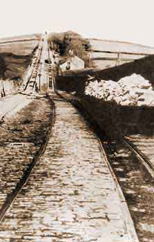 | 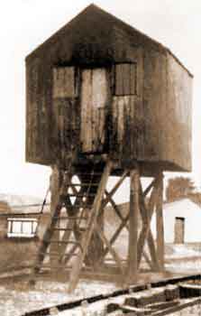 |
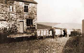
| The bottom of the inclined plane, early 20th century. A gang of waggons, loaded with limestone, stands in a siding on the right. A gang of loaded waggons is descending the plane and this can be seen just above Tanpit Cottage on the right. On the left-hand track, a gang of empty waggons can just be seen approaching the top of the plane. | The brakeman's box at the top of the inclined plane, Chapel-en-le-Frith, early 20th century. |
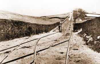 |  |
| The inclined plane, early 20th century. Waggons are moving over the plane. The brakeman's box is just visible at the top and the signal at the bottom can be seen between the two tracks. | The top of the inclined plane, 1927/28. |
 |
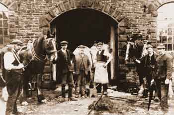 |
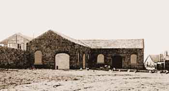
| The outbuildings at the Top o' th' Plane, 1930s. The building on the left (gable end facing) was the carpenters shop and the one on the right was the blacksmiths shop. The outbuildings are Grade II listed, List Entry No. 1249624. | The blacksmiths shop at Top o' th' Plane, c.1905. This group is the Marchington private haulage team, which operated two and three horse teams between Top o' th' Plane and the limestone quarries near Dove Holes. They carried limestone and general goods. From left to right the men are, Edwin Swain Bagshaw, Harry Fletcher, James W Lomas, Robert Joel, Joseph Marchington (owner of the team) and William Cartledge. Joseph Marchington was born and lived at Hallsteads Farm, Dove Holes Dale. Horses were bred at the farm for use on the tramway. Later, the haulage team diversified and motorised and Marchington Stone Ltd developed from this. |
Please use the Scrollbar to pan over the map of the Inclined Plane